

Bypass Diodes in Solar Panels
Bypass Diodes which in electronics we know as free-wheeling diodes, are wired in parallel with individual solar cells or panels, to provide a current path around them in the event that a cell or panel becomes faulty or open-circuited. This allows a series (called a string) of connected cells or panels to continue supplying power at a reduced voltage rather than no power at all.
Bypass diodes are connected in reverse bias between a solar cells (or panel) positive and negative output terminals and has no effect on its output. Ideally there would be one bypass diode for each solar cell, but this can be rather expensive so generally one diode is used per small group of series cells.
A “solar panel” is constructed using individual solar cells, and solar cells are made from layers of silicon semiconductor materials. One layer of silicon is treated with a substance to create an excess of electrons. This becomes the negative or N-type layer. The other layer is treated to create a deficiency of electrons, and becomes the positive or P-type layer similar to transistors and diodes.
When assembled together with conductors, this silicon arrangement becomes a light-sensitive PN-junction semiconductor. In fact Photovoltaic Solar Cells or PV’s as they are more commonly called, are no more than big, flat photo sensitive diodes.
Photovoltaic solar cells convert the photon light around the PN-junction directly into electricity without any moving or mechanical parts. PV cells produce energy from sunlight, not from heat. In fact, they are most efficient when they are cold!.
When exposed to sunlight (or other intense light source), the voltage produced by a single solar cell is about 0.58 volts DC, with the current flow (amps) being proportional to the light energy (photons). In most photovoltaic cells, the voltage is nearly constant, and the current is proportional to the size of the cell and the intensity of the light.
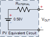 The equivalent circuit of a PV, shown on the left, is that of a battery with a series internal resistance, RINTERNAL, similar to any other conventional battery. However, due to variations in internal resistance, the cell voltage and therefore available current will vary between photovoltaic cells of equivalent size and structure, connected to the same load, and under the same light source so this must be accounted for in the solar panel assemblies you buy.
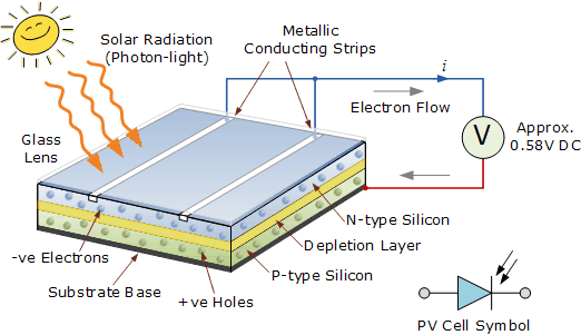
The silicon wafer of the photovoltaic solar cell that faces the sunlight consist of the electrical contacts and is coated with an anti-reflective coating that helps absorb the sunlight more efficiently. Electrical contacts provide the connection between the semiconductor material and the external electrical load, such as a light bulb or battery.
When sunlight shines on a photovoltaic cell, photons of light strike the surface of the semiconductor material and liberate electrons from their atomic bonds. During manufacture certain doping chemicals are added to the semiconductors composition to help to establish a path for the freed electrons. These paths creates a flow of electrons forming an electrical current which starts to flow over the surface of the photovoltaic solar cell.
Metallic strips are placed across the surface of a photovoltaic cell to collect the electrons which form the positive (+) connection of the cell. The back of the cell, the side away from the incoming sunlight consists of a layer of aluminium or molybdenum metal which forms the negative (–) connection to the cell. Then a photovoltaic solar cell has two electrical connections, one positive, on the top, and one negative, at the bottom as shown.
Photovoltaic Solar Cell Construction
The type of solar power produced by a photovoltaic solar cell is DC the same as from a battery. Most photovoltaic solar cells produce a “no load” open circuit voltage of about 0.5 to 0.6 volts when there is no external circuit connected. This output voltage ( VOUT ) depends very much on the load current ( I ) demands of the PV cell.
For example on very cloudy or dull day the current demand would be low and so the cell could provide the full output voltage, but at a reduced output current. But as the current demand of the load increases a brighter light (solar radiation) is needed at the junction to maintain a full output voltage, VOUT.
However, there is a physical limit to the maximum current that a single photovoltaic solar cell can provide no matter how intense or bright the suns radiation is. This is called the maximum deliverable current and is symbolised as IMAX.
The IMAX value of a single photovoltaic solar cell depends upon the size or surface area of the cell (especially the PN-junction), the amount of direct sunlight hitting the cell, its efficiency of converting this solar power into a current and of course the type of semiconductor material that the cell is manufactured from either silicon, gallium arsenide, cadmium sulphide or cadmium telluride etc.
So when selecting blocking diodes or bypass diodes to connect to solar cells or panels, this maximum current value, IMAX needs to be taken into account.
Diodes in Photovoltaic Arrays
The PN-junction diode acts like solid state one way electrical valve that only allows electrical current to flow through themselves in one direction only. The advantage of this is that diodes can be used to block the flow of electric current from other parts of an electrical solar circuit. When used with a photovoltaic solar panel, these types of silicon diodes are generally referred to as Blocking Diodes.
Bypass Diodes are used in parallel with either a single or a number of photovoltaic solar cells to prevent the current(s) flowing from good, well-exposed to sunlight solar cells overheating and burning out weaker or partially shaded solar cells by providing a current path around the bad cell. Blocking diodes are used differently than bypass diodes.
Bypass diodes in solar panels are connected in “parallel” with a photovoltaic cell or panel to shunt the current around it, whereas blocking diodes are connected in “series” with the PV panels to prevent current flowing back into them. Blocking diodes are therefore different than bypass diodes although in most cases the diode is physically the same, but they are installed differently and serve a different purpose. Consider our photovoltaic solar array below.
Bypass Diodes in Photovoltaic Arrays
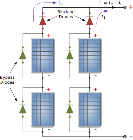
As we said earlier, diodes are devices that allow current to flow in one direction only. The diodes coloured green above are “bypass diodes”, one in parallel with each solar panel to provide a low resistance path. Bypass diodes in solar panels and arrays need to be able to safely carry this short circuit current.
The two diodes coloured red are referred to as the “blocking diodes”, one in series with each series branch. Blocking diodes are different than bypass diodes, but in most cases the two diodes are physically the same. However they are installed differently and serves a different purpose.
These blocking diodes, also called a series diode or isolation diode, ensure that the electrical current only flows in one direction “OUT” of the series array to the external load, controller or batteries.
The reason for this is to prevent the current generated by the other parallel connected PV panels in the same array flowing back through a weaker (shaded) network and also to prevent the fully charged batteries from discharging or draining back through the array at night. So when multiple solar panels are connected in parallel, blocking diodes should be used in each parallel connected branch.
Generally speaking, blocking diodes are used in PV arrays when there are two or more parallel branches or there is a possibility that some of the array will become partially shaded during the day as the sun moves across the sky. The size and type of blocking diode used depends upon the type of photovoltaic array.
Two types of diodes are available as bypass diodes in solar panels and arrays: the PN-junction silicon diode and the Schottky barrier diode. Both are available with a wide range of current ratings. The Schottky barrier diode has a much lower forward voltage drop of about 0.4 volts as opposed to the PN diodes 0.7 volt drop for a silicon device.
This lower voltage drop allows a savings of one full PV cell in each series branch of the solar array therefore, the array is more efficient since less power is dissipated in the blocking diode. Most manufacturers include both blocking diodes and bypass diodes in their solar panels simplifying the design.


