

Binary Numbers
In digital electronics, binary numbers are the flow of data or information in the form of zeros (0) and ones (1), which is used by digital system or computers. Unlike a linear, or analogue circuits, such as AC amplifiers, which process signals that are constantly changing from one value to another, for example amplitude or frequency, digital circuits process signals that contain just two voltage levels or states, labelled, Logic “0” and Logic “1”.
Generally, a logic “1” represents a higher voltage, such as 5 or 12 volts, which is commonly referred to as a HIGH value, while a logic “0” represents a low voltage, such as 0 volts or ground, and is commonly referred to as a LOW value. These two discrete voltage levels representing the digital values of “1’s” (one’s) and “0’s” (zero’s) are commonly called: Binary digits, and in digital circuits and applications they are normally referred or known as binary BITS.
Binary Bits of Zeros and Ones
Because there are only two valid Boolean values for representing either a logic “1” or a logic “0”, makes the system of using Binary Numbers ideal for use in digital or electronic circuits and systems.
The binary number system is a Base-2 numbering system which follows the same set of rules in mathematics as the commonly used decimal or base-10 number system. So instead of powers of ten, ( 10n ) for example: 1, 10, 100, 1000 etc, binary numbers use powers of two, ( 2n ) effectively doubling the value of each successive bit as it goes, for example: 1, 2, 4, 8, 16, 32 etc.
The voltages used to represent a digital circuit can be of any value, but generally in digital and computer systems they are kept well below 10 volts. In digital systems theses voltages are called “logic levels” and ideally one voltage level represents a “HIGH” state, while another different and lower voltage level represents a “LOW” state. A binary number system uses both of these two states.
Digital waveforms or signals consist of discrete or distinctive voltage levels that are changing back and forth between these two “HIGH” and “LOW” states. But what makes a signal or voltage “Digital” and how can we represent these “HIGH” and “LOW” voltage levels. Electronic circuits and systems can be divided into two main categories.
- Analogue Circuits – Analogue or Linear circuits amplify or respond to continuously varying voltage levels that can alternate between a positive and negative value over a period of time.
- Digital Circuits – Digital circuits produce or respond too two distinct positive or negative voltage levels representing either a logic level “1” or a logic level “0”.
Analogue Voltage Output
A simple example of the differences between an analogue (or analog) circuit and a digital circuit are shown below:
Analogue Voltage Output Representation
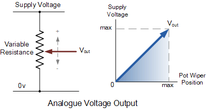
This is an analogue circuit. The output from the potentiometer varies as the wiper terminal is rotated producing an infinite number of output voltage points between 0 volts and Vmax. The output voltage can vary either slowly or rapidly from one value to the next so there is no sudden or step change between two voltage levels thereby producing a continuously variable output voltage. Examples of analogue signals include temperature, pressure, liquid levels and light intensity.
Digital Voltage Output
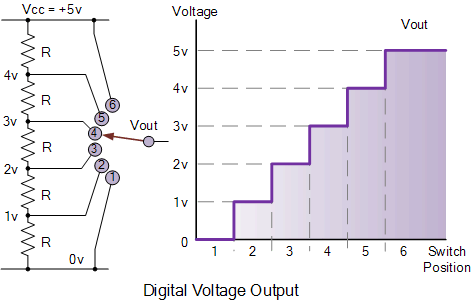
In this digital circuit example, the potentiometer wiper has been replaced by a single rotary switch which is connected in turn to each junction of the series resistor chain, forming a basic potential divider network. As the switch is rotated from one position (or node) to the next the output voltage, Vout changes quickly in discrete and distinctive voltage levels representing multiples of 1.0 volts on each switching action or step, as shown in the output graph.
So for example, the output voltage will be 2 volts, 3 volts, 5 volts, etc. but NOT 2.5V, 3.1V or 4.6V. Finer output voltage levels could easily be produced by using a multi-positional switch and increasing the number of resistive elements within the potential divider network, therefore increasing the number of discrete switching steps.
Digital Voltage Output Representation
Then we can see that the major difference between an analogue signal or quantity and a digital quantity is that an “Analogue” quantity is continuously changing over time while a “Digital” quantity has discrete (step by step) values. “LOW” to “HIGH” or “HIGH” to “LOW”.
A good example of this would be a light dimmer in your house that varies the lights intensity (brightness) up or down as it is rotated between fully-ON (maximum brightness) and fully-OFF, producing an analogue output that varies continuously. While on the other hand, with a standard wall mounted light switch, the light is either “ON” (HIGH) or it is “OFF” (LOW) when the switch is operated. The result is that there is no in between producing a form of ON-OFF digital output.
Some circuits combine both analogue and digital signals such as an analogue to digital converter (ADC) or a digital to analogue converter (DAC). Either way, the digital input or output signal represents a binary number value equivalent of an analogue signal.
Digital Logic Levels
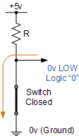
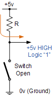
In all electronic and computer circuits, only two logic levels are allowed to represent a single state. These levels are referred to as a logic 1 or a logic 0, HIGH or LOW, True or False, ON or OFF. Most logic systems use positive logic, in which case a logic “0” is represented by zero volts and a logic “1” is represented by a higher voltage. For example, +5 volts for TTL logic as shown.
Digital Value Representation
| First State | Second State |
| Logic “0” | Logic “1” |
| LOW | HIGH |
| FALSE | TRUE |
| Low Level Voltage Output | High Level Voltage Output |
| 0V or Ground | +5 Volts |
 |
 |
Generally the switching from one voltage level, “0” to “1” or “1” to “0” is made as quickly as possible to prevent miss switching of the logic circuit. In standard TTL (transistor-transistor-logic) IC’s there is a pre-defined range of input and output voltage limits for defining what exactly is a logic “1” value and what is a logic “0” value as shown below.
TTL Input & Output Voltage Levels
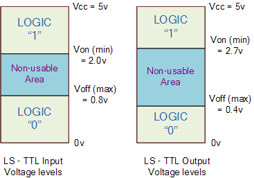
Then, when using a +5 volt supply any voltage input between 2.0v and 5v is recognised as a logic “1” value and any voltage input of below 0.8v is recognised as a logic “0” value. While the output of a logic gate between 2.7v and 5v represents a logic “1” value and a voltage output below 0.4v represents a logic “0” value. This is called “positive logic” and is used in these digital logic tutorials.
Then binary numbers are commonly used in digital and computer circuits and are represented by either a logic “0” or a logic “1”. Binary numbering systems are best suited to the digital signal coding of binary, as it uses only two digits, one and zero, to form different figures. So in this section about Binary Numbers we will look at how to convert decimal or base-10 numbers into octal numbers, hexadecimal numbers, and binary numbers.
So in the next tutorial about Binary Numbers and the binary number system we will look at converting decimal numbers into binary numbers and vice versa and introduce the concept of the Byte and the Word to represent the parts of a much larger binary number.


