

Are you ready to make your first electronics project? If the answer is YES then you are at the right place to learn all the basics about building your project.
So let’s start
Before making a new project, you require some basic tools and knowledge of how to use them to complete your project. Most important and commonly used tool which you require is soldering iron and soldering wire. You will also need some more tools like wire-cutters, wire-strippers and a pair of small pliers. Some other tools are also useful although they are not essential at starting stage.
ESSENTIAL TOOLS REQUIRED FOR BASIC ELECTRONICS-
Soldering iron – A soldering iron is a hand tool used for soldering the components. It is used to provide heat to melt the solder wire so that it can flow between the component and PCB to join the lead of component to the board.
If you are beginner or doing soldering for first time, we will suggest you to use solder iron of power rating between 15-25 watts which is suitable for most of the soldering work. Higher watt soldering iron is also available in market. Keep in mind higher wattage iron does not mean that it will melt the solder wire fast.
Bit size – While selecting the size of bit, one must take care that bit size should be slightly smaller than the pad you are soldering. Bit of soldering iron vary in shape, size and according to the type of work you are doing. For example-
1. Pyramid tips with a triangular flat face is useful for soldering sheet metal.
2. Fine conical or tapered chisel tips are typically used for electronics work.
If you are doing soldering for first time we will suggest you to use Spade shape bit.
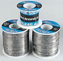
Solder wire – Solder wire is a fusible metal alloy use to solder the components with the PCB. Solder wire which you are using should have its melting point below the work piece. It is a metal or metallic alloy. The most common used alloy is combination of tin and lead in some definite proportion. Melting points of some common solder wire are as follows-
Tin/Lead Melting Point
40/60 230 degrees C
50/50 214 degrees C
60/40 190 degrees C
63/37 183 degrees C
95/5 224 degrees C
While purchasing the solder wire one must take care of the application for which we are purchasing like -If you need to solder very fine electrical circuits you should use the solder wire in the range from .01-inch to .05-inch, and if you want to solder household electrical work you should go for .5-inch.
For beginner we will suggest you to use solder wire in the range of 20 -22 SWG (standard wire gauge).
Flux – Flux is used a s a clea ning, flowing, purifying agent. It is basically used to remove the traces of water vapors or moisture present on the PCB before soldering because this may lead to bad soldering of joints. Commonly used fluxes are:
[sam id=”5″ codes=”true”]
1. Ammonium chloride for soldering tin.
2. Hydrochloric acid and zinc chloride for iron.
3. Braze for welding ferrous metal.
Cutting pliers – They are used when you have soldered the component and want to cut the remain lead of the component. It has blade at one side so that you can easily chop the remaining part after soldering from PCB.

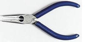
Long nose pliers – It is used for bending the leads of components or can be used to hold the component while soldering as component become hot due to the heat from soldering iron. It can also be used to hold the nuts while tightening the bolts.
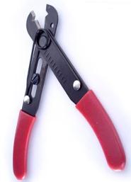
Wire strippers – It is used to cut or strip the insulation above the wire. When we solder the PCB sometimes it happen we require to strip the multi strain wire or to cut the leads of the components there we can use this tool.
Track cutter – It can be used to cut the unwanted tracks which are joined during the process of soldering. Being an beginner it happens many times while soldering the components on PCB.
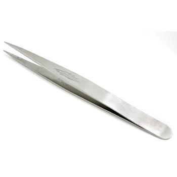
Tweezers – It is a very useful tool for holding the small components and for removing the IC from the breadboard or from the IC base. It is also useful for holding thin wires.
Magnifying glass – It can be used to see the small markings on components and also for examining circuit board traces and solder connections. You should solder under magnification using a magnifying work lamp, it is useful if you are doing soldering of Surface Mount Components.
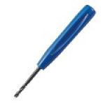
De-Solder tool – Useful when you want to remove the solder joint for whatever reasons. You will require the following tools-
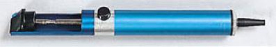
De-solder pump – By mistake you have placed the wrong component, or you have put extra solder or you want to replace the component whatever may be the reason, you will be requiring this de solder pump. De soldering pump is a spring-loaded suction pump with Teflon nozzle.
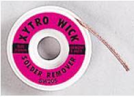
De-soldering wick – It is a copper braid woven using fine copper wire and it also contains flux. It comes in rolls of one to one-and-a-half meter length. To de solder the joint, just place the copper wick over the joint to be de soldered and put the hot iron above it. Due to heat from hot solder, iron solder melts it and get trapped in to the copper wick. Take special prevention on the components which are easily damage by heat.
TEST EQUIPMENT: USING MULTI METER
Multi-meter – This is the most basic equipment you should have with you. If your circuit does not work properly you can troubleshoot it with the help of multi-meter. Multi-meters are of two types:
1.Digital
2.Analog – Analog multi-meters are old Fashioned — but still useful
Multi meters come with a pair of test leads like black for the ground connection and Red for the positive connection.
You can use a multi-meter to take a variety of electrical measurements. With the help of multi-meter you can perform following operation –
a)Measure AC voltages
b)Measure DC voltages
c)Measure resistance
d)Measure current going through a circuit
e)Measure continuity (whether a circuit is broken or not)
f)Test the operation of diodes and transistors
My recommendation: Have you own multi meter
Power Supply – It is also very useful for testing your new work piece. We will suggest you have variable power supply of 20V, with maximum current rating of 1A is suitable for various jobs. Today in market different ranges of voltage adaptor are also available you can also purchase that. Or you can make your own power supply.
MOUNTING OF COMPONENTS
Insert the components – Try to insert components in order of their size, smallest first because it can be difficult to insert small components if larger ones are in the way. If any wire links have to be soldered then solder it first (Know more about soldering). Following order may be followed while soldering the components-
1. Jumpers (wire connection)
2.Resistors
3. IC base
4.Capacitors
5.Inductors
6.Transistor
7.LED
8.Triac
9.Voltage regulators
10.Transformer
Make sure – Components such as resistors should sit flat on the board, leaving no gap between the component and the board. But the component such as transistor, voltage regulator i.e. that dissipates heat should be mounted little bit above the PCB so they are able to release their heat easily. This will not only make you PBC looks good but also give components some protection.
Be systematic – Follow the order mentioned above for inserting the component. And if you think that a component is not properly soldered or a joint look bad, carefully remove it and solder it again.
Check – You have connected the components on the right place with correct polarity twice on the board. Like check the value of resistor with help of multi-meter, check whether LED or diode you are going to mount is good or bad. This will save your time while troubleshooting.
ALWAYS CHECK THE POLARITY OF THE BATTERY AND ANY POLARISED COMPONENTS (CAPACITORS, TRANSISTORS ETC.) BECAUSE THIS MAY DAMAGE YOUR WHOLE CIRCUITS!
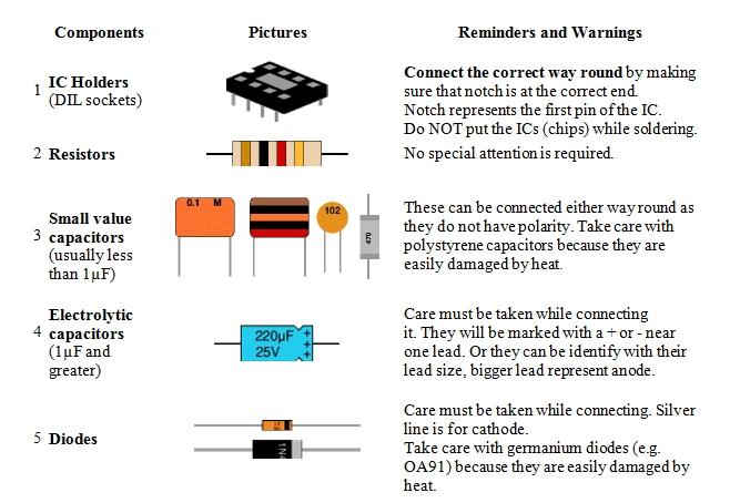
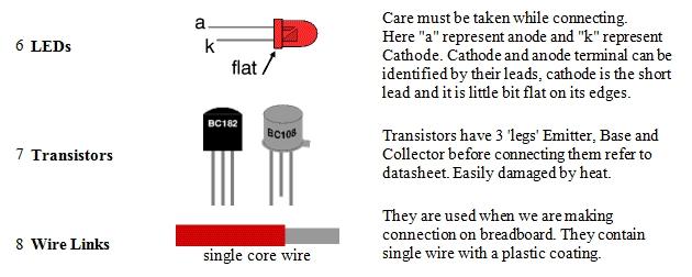
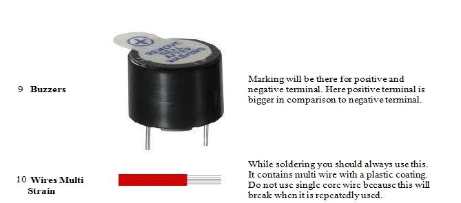
Some components require special attention commonly known components with their precaution are described in table below-
SOLDERING
Benefits of Pre-Bending
Place the tip – Of the iron on the lead which you want to solder and another side place the solder wire. Due to the heat produce from soldering iron solder melts and stick to leads of the component and board.
Wait a second – Or two for the lead to heat up. Do not leave the iron for long duration otherwise it will harm the components and board.
If you need to remove the solder–Use a de-soldering pump or solder braid, or melt the extra solder and remove the component with the help of tweezers. Try again – practice will make you perfect!
When the joint is OK– Now it is the time to cut the leads of the components with the cutter so that your board or PCB will look neat and clean.
Rule #1: It is necessary to make good mechanical connection before you start soldering.
Rule #2: Do soldering only when iron is hot.
Rule #3: Always apply solder on the leads of the component do not just melt it.
Rule #4: Always inspect the connection after soldering.
When you are sure everything is correct, apply power supply and see if the circuit gives you desire output.
If it does not work as expected, or does not work at all, don’t feel sad. The chances may be you have done some silly mistake. Firstly disconnect the power supply.


