

Introduction:
We turn On the lights in our washroom when we enter it and turn them off when we leave. We sometimes forget to turn Off the lights after leaving the washroom. This may lead to power wastage and also the lifetime of the lights may decrease. To avoid these problems, we are going to make a circuit which automatically turns On the lights when a person enters the washroom and it automatically turns it Off when he leaves it.
By automating this, there are many advantages like, the person need not care to turn On the light always when he is using the washroom. The circuit which we are doing does it automatically for that person. Also, the person need not turn it off after using the washroom. There is no fear that he forgets to turn it Off. The circuit is also designed to consume lesser power so that the circuit can be used in any household or public washrooms without worrying about the power bills.
Automatic Washroom Light Switch Circuit Diagram:
 Description:
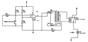
The operation of the circuit is as follows. When the door of the washroom is opened and closed, the circuit turns switches On the light using a relay. When the door opens and closes for the second time, the circuit turns Off the light by turning off the relay.
The element which is used to detect the opening and closing of the door is a reed switch. There are two types of reed switches. We are using the one which will be closed in normal state and open when there is a magnetic field nearby. A reed switch electrically is just a relay kind of component but unlike a relay which activates when a coil voltage is supplied, the reed switch activates when a magnetic field is detected in the vicinity. The circuit is given a power supply of 9V. The pin-16 of IC 4017 is given 9V. The pin-8 of 4017 is given to ground.
The circuit uses IC 741 op-amp as a comparator arranged such that its output is high by default when the door is closed. The circuit is attached to the door frame whereas a permanent magnet is attached to the door in such a way that it comes closer to the reed switch when it is closed. The IC 4017 is made to alternate between each door open and door close. When the door is opened and closed for one time, the circuit turns On the relay and the the Light turns ON. When the door is opened and closed for the next time, the circuit turns Off the relay and the light turns off. The IC 4017 is capable of counting upto nine counts but we are restricting it to count only two and reset back. The ability of this IC to adjust the count value as desired helped us in this project to use it as a one bit counter.
When the door is closed, the reed switch opens and hence the op-amp output which is the 6th pin of IC 741 is HIGH. When the door is closed, the pin-6 of IC 741 is turned Off. When the door is closed back, it triggers the IC 4017 decade counter and hence the relay toggles ON and OFF for each door open and close operation.


