

The Arduino Pro Mini is an ATmega168 based microcontroller board. The board comes with built-in arduino bootloader. It has 14 digital input/output pins (of which 6 can be used as PWM outputs), 8 analog inputs, an on-board resonator, a reset button, and holes for mounting pin headers. The board can be connected to the PC using USB port and the board can runs on USB power.
There are two version of the Pro Mini. One runs at 3.3V and 8 MHz, the other at 5V and 16 MHz.
| Arduino Pro Mini DETAILS | |
| Microcontroller | ATmega168 |
| Operating Voltage | 3.3V or 5V |
| Input Voltage | 3.35 -12 V (3.3V model) or 5 – 12 V (5V model) |
| Digital I/O Pins | 14 (of which 6 provide PWM output) |
| Analog Input Pins | 8 |
| DC Current per I/O Pin | 40 mA |
| Flash Memory | 16 KB (of which 2 KB used by bootloader) |
| SRAM | 1 KB |
| EEPROM | 512 bytes |
| Clock Speed | 8 MHz (3.3V model) or 16 MHz (5V model) |
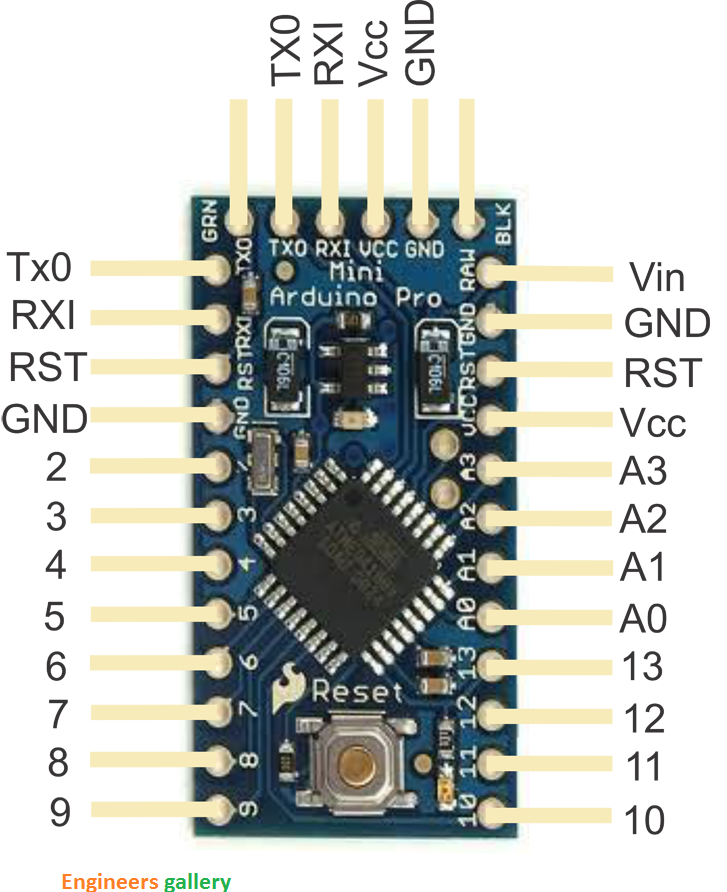
| Arduino Pro Mini PINOUT | |
| RAW | For supplying a raw (regulated) voltage to the board |
| VCC | The regulated 3.3 or 5 volt supply |
| GND | Ground pins |
| RX | Used to receive TTL serial data |
| TX | Used to transmit TTL serial data |
| 2 and 3 | Digital I/O pins. These pins can also be configured to trigger an interrupt on a low value, a rising or falling edge, or a change in value |
| 3, 5, 6, 9, 10, and 11 | Digital I/O pins. They can also be configured to provide 8-bit PWM output |
| 10, 11, 12 and 13 | Digital I/O pins. They can also be configured as SPI pins;10 – (SS), 11 – (MOSI), 12 – (MISO) and 13 – (SCK) |
| A0 to A3 | Analog input pins |
| A4 and A5. | Analog input pins. They can also be used as IIC pins;A4 – (SDA) and A5 – (SCL). |
| A6 and A7 | Analog input pins |
| Reset | The microcontroller can be reset by bringing this pin low |


