

Introduction
In fact, we managed to achieve a small 1.1 uA current with both of them sleeping. Also in our circuit there were a PCF8563 real-time clock module and one AT24C64 EEPROM memory. Now, to proceed with our smartwatch project we need to add sensors, such as an accelerometer, compass and pressure sensor. This article is about how to add them, read the variables and keep saving power.
Which sensor to use
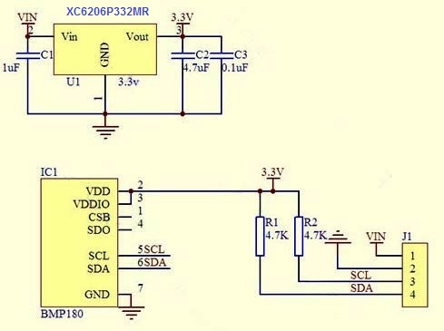
Now that we have a watch running, I mean, a microcontroller reading a real-time clock module and throwing the data to a display, we can add some features to it! How about a pressure sensor? With a pressure sensor such as the BMP180 (or the BMP080), it is possible to get also the temperature from the environment, and with both information, the chip can estimate the altitude in which the person is.
Another very useful sensor could be the digital compass. The HMC5883L is an I2C compatible, very tiny compass that can point which direction the smartwatch is facing. The idea to put a compass was initially to help my sister, as she is a biologist an often have to enter forests or areas with dense vegetation. With a watch that has a very long battery duration, now she won’t get lost.
Another great sensor you must add to your device is the MPU6050 accelerometer. There is the possibility to use the MPU9150, which already has a compass inside it. However, the MPU9150 doesn’t have a very good library available online and is way more expensive than his cousin, the 6050. With the accelerometer data, the Atmega328p can work as a step counter. In possession of the number and frequency of the steps, the watch can estimate also the distance travelled and the calories spent on a daily basis. The sensors main features:
-
BMP180
- Senses:
- Pressure;
- Temperature;
- Altitude;
- Features:
- Pressure range: 300 to 1100 hPa;
- RMS noise 0.06 hPa, typ. (ultra-low power mode);
- 02 hPa, typ. (ultra-high resolution mode);
- I2C interface;
- Temperature: ±1 °C, typ.;
- Current (at 1Hz): 3 μA (ultra-low power mode);
- Current 32 μA, typical (advanced mode);
- Stand-by current 0.1 μA, typical;
- Supply voltage VDD 62 … 3.6 V;
- Operation temperature -40 to +85 °C;
- Maximum supply voltage all pins -0.3 +4.25 V;
- Package dimensions 6 x 3.8 x 0.93 mm³.
- Senses:
-
HMC5883L:
- Responsible for:
- X, Y, Z compass;
- Features:
- Fast 160 Hz maximum output rate;
- Software and algorithm support available;
- I2C digital interface;
- Low voltage operation (2.16 to 3.6V);
- Low power consumption (100 μA);
- Idle mode current 2 μA;
- 3-Axis magneto resistive sensors;
- Absolute maximum supply voltage 4.8 Volts;
- Responsible for:
-
MPU6050:
- Responsible for:
- X, Y, Z accelerometer;
- X, Y, Z gyroscope;
- Step counter;
- Calories counter;
- Distance;
- Features:
- Integrated 16-bit ADCs enable simultaneous sampling of gyros;
- Temperature stability reduces the need for user calibration;
- Digitally-programmable low-pass filter;
- Maximum supply voltage, VDD -0.5V to +6V;
- Gyroscope operating current: 3.6mA;
- Gyroscope standby current: 5µA;
- Accelerometer normal operating current: 500µA;
- Accelerometer low power current: 10µA at 1.25Hz;
- Orientation detection and signaling;
- Tap detection;
- High-G interrupt;
- 400kHz fast mode I2C;
- Digital Motion Processing engine supports 3D Motion Processing and gesture recognition algorithms;
- Responsible for:
Choose the board or make your own
It is possible to find these sensors on its own board separately or together on the same board. To test them on our breadboard, it is easier to buy each sensor on its own custom PCB. The downside is that these pcbs come with already soldered components that you do not want. For example, all these boards sold on EBay come with voltage regulators to guarantee the maximum voltage to the chips will be at 3.3V. However, these regulators consume a lot of power and, if we are making an application that keeps its voltage fixed, for instance, like a smartwatch powered by a lithium battery, we do not need them. To test the minimum current your watch will use, you will probably want all useless components out of your board. Another example are the LEDs that are placed just to show that the board is on! Totally useless. Each LED will consume easily 1.5mA, while we are trying to make the watch run with only 100uA, or 15 times lower than that. Now imagine each sensor using one LED just to show you they are on.
The problem is that it is too much complicated to make your own SMD board without the LED and voltage regulator, so you can buy a board on EBay, take out those components and short circuit some places and everything is fine. When the time comes to make the SMD board for the smartwatch, then you can make your own with all the pieces together. To use these sensors, the boards I recommend are:
-
GY-521 (MPU6050):
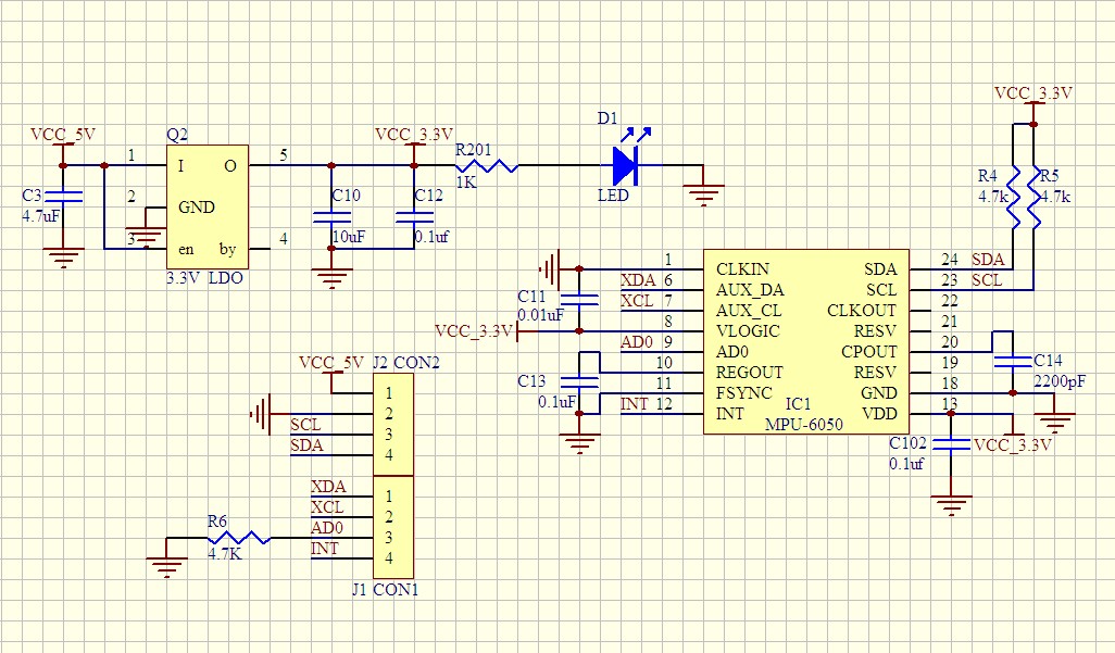
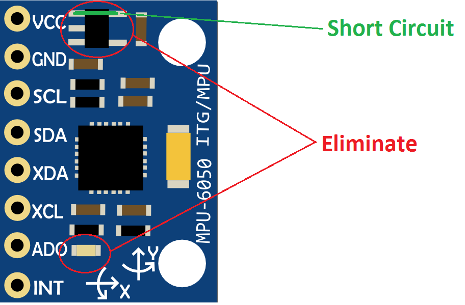 This module supports higher voltages than 3.3V, because it has a voltage regulator (the 3.3V LDO component from the figure above). To use it with low power mode, the user has to desolder the regulator, short-circuiting the 5V and 3.3V connectors (where the regulator was). In addition, it is good to remove the LED. This is show on the figure at the left.
-
GY-271 and 273 (HMC5883L):
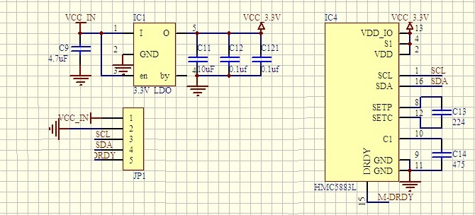
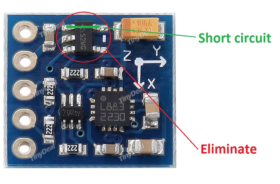 Along with the GY-521, this module supports higher voltages than 3.3V. To use it with low power mode, the user has to desolder the regulator, short-circuiting the 5V and 3.3V connectors (where the regulator was). This one however does not have LED. Watch out that after taking away the regulator you should not program the Arduino with these boards connected, because the UNO will use its 5V VCC to program the Pro Mini (Arduino as ISP). This version has an I2C NMOS, while the GY-273 does not.
-
GY-68 (BMP180):
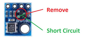
This board is the pressure sensor’s equivalent for the GY-273. Just remove the regulator and short circuit 5V and 3.3V.
-
GY-87 (all in one):
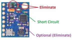

This is a good one. This board has all the sensors in it. It has the accelerometer MPU6050, the compass HMC5883L, and the pressure sensor BMP180. However, the board comes with a voltage regulator and LED. You have to take both of them off to work on low power. Moreover, to convert the I2C signal from 5V to 3.3V, it has the I2C NMOS. If you do not remove it, your circuit will not be the best possible. To remove it is easy. The tough part is to short circuit correctly the terminals, because you would have to connect SDA to H_SDA, SCL to H_SCL and 5V to 3.3V, all on that minuscule space between the pads. For me, I was happy just to remove the regulator and the LED and left everything else the way it was. It worked the same way. It was possible to lower the current on standby from 900 uA to only around 118 uA. Perhaps, if removed, this could lower to far below 100 uA.
Connect the board
Simple enough just connect 3.3V VCC from breadboard to VCC, GND to GND (lol), SCL and SDA. The only different pin is the INTA from the accelerometer that should be connected to the PIN number 5 from the Atmega328p (digital input 3). This is because this output from the accelerometer will be used as an interrupt pin to the Arduino to wake it up from sleep on each step that the sensor reads. For example, the watch will be always sleeping. Just two events will be able to wake it up from sleep. A button being pressed, that means the person wants to know the time, or the accelerometer sending a signal telling the chip that the user made another step. On this case, the microcontroller add one step to its step counter, calculates the calories and then go to sleep again! Cool!
OUTPUT WINDOW


