
")
Arduino Based Voltmeter
[nextpage title=”Description”] This is a project based on Arduino board which can measure the unknown AC and DC voltages. When we connect the unknown voltage on the breadboard circuit, the 16*2 LCD displays the voltage value. The project uses an Arduino pro mini board whose ADC feature is used along with the concept of Voltage Divider circuit to develop thisVoltmeter.
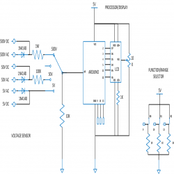
Architecture of the project
The entire project can be divided into three basic blocks;
1) AC/DC Voltage Sensor Unit
2) Processor Unit
3) Display Unit
The Sensor Unit takes two inputs, DC voltage and AC voltage. The Sensor Unit scales down the input DC and AC voltages into a DC voltage in the range of 0 to 5 V and provides the same as output.
The Processor Unit takes input voltage in the range of 0 to 5V. This unit takes the Sensor Unit’s output as input voltage and uses the ADC to read this voltage. An Algorithm is then applied tocalculate the voltage. The unit then sends a 4bit data to the Display Unit which includes the AC and DC voltage values.
The Display Unit takes the 4bit data from the Processor Unit and produces a 16×2 display for AC and DV voltages.
1) AC/DC Voltage Sensor Unit
A basic voltage divider circuit is used as the AC/DC Sensing Unit to scale down the input DC and AC voltages into a DC voltage in the range of 0 to 5 V. The Processor Unit can read this scaled down voltage and calculate the actual AC/DC voltages.
Design the value of R1:
Let us first select a maximum voltage that could be measured as 500V. When we apply 500V as ‘V’, the ‘V2’ should not be more than 5V and hence ‘V1’ will be 500 – 5 = 495V. At very high voltages like 495, the first thing to be taken care of is the power rating of the resistor. We are using resistors with the power rating 0.25W, and the power consumed by the resistor ‘R1’ should be less than this, otherwise the resistors get heated up and catch fire.
The equation for power is, P = V12 / R1.
Where;
P Power rating of the resistor
V Voltage across the resistor
R Resistance of the resistor
For the resistor R1 with power rating 0.25 W and 495 V across it,
0.25 = 495 * 495 / R1
Or, R1 = 980100 ohms, take 1 M ohm standard resistor.
Design the value of R2:
Now the value of R2 can be calculated using the previous equation, V = V2 * (1 + R1 / R2) as follows;
R2 = R1 / ((V / V2) – 1)
R2 = 1000000 / ((500 / 5) – 1)
R2 = 10101 ohms, take 10K ohm standard resistor.
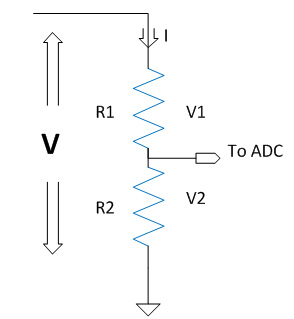
The voltage ‘V2’ is a fraction of the actual applied voltage ‘V’. The applied voltage ‘V’ can be calculated from the fraction of applied voltage ‘V2’ with the help of the following equation.
DC voltage, Vdc = V2 * (1 + (R1 / R2))
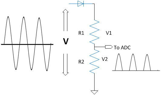
AC voltage as input:
When we are applying an AC voltage we use a rectifier diode in series with the Voltage divider circuit to prevent the negative cycles from entering the circuitry. No need for step down transformers because we are already getting a voltage ‘V2’ in the range of 0 to 5 V only, across R2.
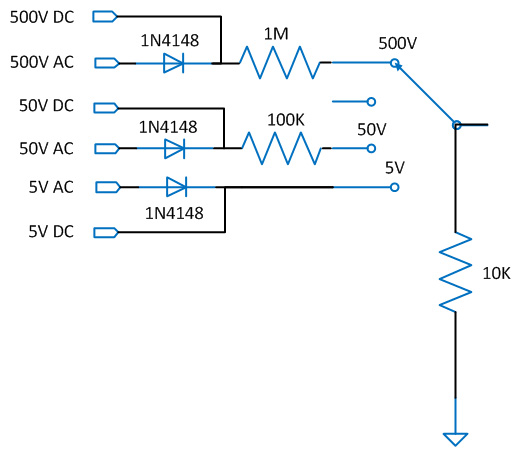
Requirement for Range selector:
We require multiple ranges in avoltmeter due to the error appears in readings because of Resistance Tolerance.
a) Decrease in the ratio of R1/R2 decreases the error
b) There is a limit beyond which the R1/R2 cannot decrease further:
To measure different values of V with minimum error we need different set of R1 with a common R2. The voltage V whose value need to be measured is connected with an R1 which gives the least ratio of R1/R2, taking care of the fact that V2 should not go above 5V range.
(R1 / R2) > (V / 5) – 1
For example to measure V = 500V, R1 / R2 > 99, hence we can use the set R1 = 1M and R2 = 10K which gives R1 / R2 = 100.
[/nextpage]
[nextpage title=”Code”]
#include <LiquidCrystal.h>
LiquidCrystal lcd(12, 11, 5, 4, 3, 2);
#define resistance_R50 100000
#define resistance_R500 1000000
#define resistance_V2 10000
#define caliberation_V2 1.1
#define range50_mul (resistance_R50 / resistance_V2) * caliberation_V2
#define range500_mul (resistance_R500 / resistance_V2) * caliberation_V2
#define resistance_Ri 10
#define resistance_Cr 100000
#define resistance_Rb 100000
#define resistance_Re 10
#define resistance_R2 1000
int adc_value = 0;
int voltage_peak_value = 0;
int discharge_voltage_V0 = 0;
int discharge_voltage_V1 = 0;
float voltage_average_value = 0;
float dc_voltage_V0 = 0;
float ac_voltage_V0 = 0;
float dc_voltage_V1 = 0;
float dc_voltage_V2 = 0;
float ac_voltage_V1 = 0;
float dc_current_I0 = 0;
float dc_current_I1 = 0;
float ac_current_I0 = 0;
float dc_power = 0;
float ac_power = 0;
float npn_pnp_hfe = 0;
float capacitance = 0;
unsigned long resistance;
unsigned long sample_count = 0;
unsigned long discharge_time_T0 = 0;
unsigned long discharge_time_T1 = 0;
char fn0 = 6;
char fn1 = 7;
char fn2 = 8;
char rn0 = 9;
char rn1 = 10;
char rn2 = 13;
char function_select [4];
char range_select [4];
void setup()
{
lcd.begin(16, 2);
lcd.print(” EG LABS “);
delay(3000);
pinMode(fn0, INPUT);
pinMode(fn1, INPUT);
pinMode(fn2, INPUT);
pinMode(rn0, INPUT);
pinMode(rn1, INPUT);
pinMode(rn2, INPUT);
}
void loop()
{
function_select [0] = digitalRead(fn0) + ‘0’;
function_select [1] = digitalRead(fn1) + ‘0’;
function_select [2] = digitalRead(fn2) + ‘0’;
function_select [3] = ‘\0’;
range_select [0] = digitalRead(rn0) + ‘0’;
range_select [1] = digitalRead(rn1) + ‘0’;
range_select [2] = digitalRead(rn2) + ‘0’;
range_select [3] = ‘\0’;
//=============================== VOLTAGE ========================================//
voltage_peak_value = 0;
for(sample_count = 0; sample_count < 5000; sample_count ++)
{
adc_value = analogRead(A0);
if(voltage_peak_value < adc_value)
voltage_peak_value = adc_value;
else;
delayMicroseconds(10);
}
dc_voltage_V0 = voltage_peak_value * 0.00488;
ac_voltage_V0 = dc_voltage_V0 / 1.414;
if ( 0 == strncmp (range_select, “01”, 2) )
{
lcd.clear();
lcd.setCursor(0, 0);
lcd.print(“[R] “);
if (range_select [2] == ‘0’)
lcd.print(” DCV”);
else
lcd.print(” ACV”);
lcd.setCursor(0, 1);
lcd.print(“0-5 “);
if (range_select [2] == ‘0’)
lcd.print(dc_voltage_V0);
else
lcd.print(ac_voltage_V0);
delay(500);
}
else;
if ( 0 == strncmp (range_select, “10”, 2) )
{
lcd.clear();
lcd.setCursor(0, 0);
lcd.print(“[R] “);
if (range_select [2] == ‘0’)
lcd.print(” DCV”);
else
lcd.print(” ACV”);
lcd.setCursor(0, 1);
lcd.print(“5-50 “);
if (range_select [2] == ‘0’)
lcd.print(dc_voltage_V0 * range50_mul);
else
lcd.print(ac_voltage_V0 * range50_mul);
delay(500);
}
else;
if ( 0 == strncmp (range_select, “11”, 2) )
{
lcd.clear();
lcd.setCursor(0, 0);
lcd.print(“[R] “);
if (range_select [2] == ‘0’)
lcd.print(” DCV”);
else
lcd.print(” ACV”);
lcd.setCursor(0, 1);
lcd.print(“50-500 “);
if (range_select [2] == ‘0’)
lcd.print(dc_voltage_V0 * range500_mul);
else
lcd.print(ac_voltage_V0 * range500_mul);
delay(500);
}
else;
//=================================================================================//
}[/nextpage]


