

ADC0808 is an 8 bit analog to digital converter with eight input analog channels, i.e., it can take eight different analog inputs. The input which is to be converted to digital form can be selected by using three address lines. The voltage reference can be set using the Vref+ and Vref- pins. The step size is decided based on set reference value. Step size is the change in analog input to cause a unit change in the output of ADC. The default step size is 19.53mV corresponding to 5V reference voltage. ADC0808 needs an external clock to operate unlike ADC0804 which has an internal clock. The ADC needs some specific control signals for its operations like start conversion and bring data to output pins. When the conversion is complete the EOC pins goes low to indicate the end of conversion and data ready to be picked up.
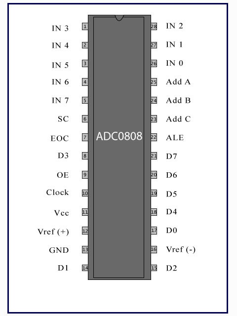
Pin Description:
| Pin No | Function | Name |
| 1 | Analog input pins | IN3 |
| 2 | IN4 | |
| 3 | IN5 | |
| 4 | IN6 | |
| 5 | IN7 | |
| 6 | Start conversion; input pin; a low to high pulse is given | SC |
| 7 | End of conversion; output pin; goes low when the conversion is over | EOC |
| 8 | Digital output bit 4 | D3 |
| 9 | Input pin; a low to high pulse brings data to output pins from the internal registers at end of conversion | Output enable |
| 10 | Clock input; to provide external clock | Clock input |
| 11 | Supply voltage; 5V | Vcc |
| 12 | Positive reference voltage | Vref(+) |
| 13 | Ground ()v) | GND |
| 14 | Digital output bit | D1 |
| 15 | D2 | |
| 16 | Negative reference voltage | Vref(-) |
| 17 | Digital output bits | D0 |
| 18 | D4 | |
| 19 | D5 | |
| 20 | D6 | |
| 21 | D7 | |
| 22 | Address latch enable; Input pin; low to high pulse is required to latch in the address | ALE |
| 23 | Address lines | AddressC |
| 24 | AddressB | |
| 25 | AddressA | |
| 26 | Analog inputs | IN0 |
| 27 | IN1 | |
| 28 | IN2 |


