

INTRODUCTION:
Industrial applications use dc motors because the speed-torque relationship can be varied to almost any useful form for both dc motor and regeneration applications in either direction of rotation. Continuous operation of dc motors is commonly available over a speed range of 8:1. Infinite range (smooth control down to zero speed) for short durations or reduced load is also common. Dc motors are often applied where they momentarily deliver three or more times their rated torque. In emergency situations, dc motors can supply over five times rated torque without stalling (power supply permitting).
The speed controller works by varying the average voltage sent to the motor. It could do this by simply adjusting the voltage sent to the motor, but this is quite inefficient to do. A better way is to switch the motor’s supply on and off very quickly. If the switching is fast enough, the motor doesn’t notice it, it only notices the average effect. Recently the multilevel pulse width modulation (PWM) converter topology has drawn tremendous interest in the power industry since it can easily provide the high power required for high power applications for such uses as static VAR compensation, active power filters, and so that large motors can also be controlled by high power adjustable frequency drives.
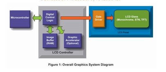
Graphics displays are gaining popularity in an increasing range of control and user interface applications in markets such as home automation, home appliance, medical and industrial. Examples include security systems, washing machines, cooking ranges, home blood pressure monitors, point-of-sale terminals, test and measurement units. Graphics displays enhance the user experience and provide detailed information with sharper images. Additionally, graphics displays enable technologies such as touch screen, leading to more effective and efficient interfaces to the applications.A typical graphics LCD system is shown in Figure 1. The system consists of a microcontroller, a LCD controller (digital-control logic, optional graphic accelerator, image buffer, gate driver), and a LCD glass.
The microcontroller normally creates, manipulates and renders graphic elements such as buttons, menus and images. If a graphic accelerator is present in the LCD controller, it provides hardware acceleration to some graphics elements and off-loads the microcontroller for other functions. The digital control logic serves as an image buffer arbiter and an electronic equivalent of picture tube for image display. A graphic LCD solution requires an image buffer to store a minimum of one image frame. Finally, the gate driver converts the digital to analog waveforms and drives the LCD glass. The gate driver is LCD glass dependent and changes based on the glass technology, size and resolution.
In current project a system is designed to control the speed and direction of dc motor based on the touch screen and graphics. This project demonstrates how touch screen can be easily interfaced to real world to control operation of complex systems like motor speed and direction. Below image shows the block diagram of motor interface to microcontroller.
BLOCK DIAGRAM:
This block diagram shows a system that can be used for bi-directional control of a brush DC motor. The current and mechanical feedback are optional depending on the application requirements. The current feedback can be used to regulate the motor torque. The mechanical feedback can be used to control motor speed or position. Scroll down to see other block diagrams for brush DC motor control.


